10r 02 7024 Relay Wiring Diagram
We hope this article can help in finding the information you. R02 series hermetically sealed relays (h−suffix) are ul recognized for class1, division 2 (hazardous locations).
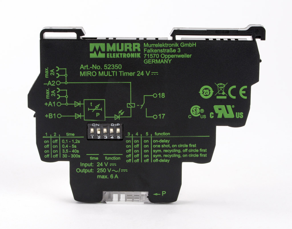
Multimode Relay Timer 0.1 to 300 seconds selectable timing range (PN 52350) AutomationDirect
Dozens of the most popular 12v relay wiring diagrams created for our site and members all in one place.
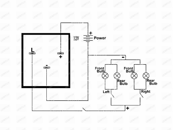
10r 02 7024 relay wiring diagram. The purpose of a relay is to automate this power to switch electrical circuits on and off at particular times. Relay can be the best option to control electrical devices automatically. Each of the different types of relays have different configurations (as they have different numbers of pins).
Buy cat® wear & maintenance parts. 12v 40a relay 4 pin wiring diagram. Switching relay wiring diagrams zone 1 zone 2 zone 3 fuse 1 amp z one 1 zone 2 zone 3 power zone 1 zone 2 n p zc h x1 x2 r com / 24 vac.
There are different kinds of relays for different purposes. Free download with regard to 12v 30 amp relay wiring diagram by admin. Each component should be set and connected with other parts in particular way.
They undergo comprehensive evaluation to ensure the hightest quality and durability standards to help maximize the life of your vehicle, and give you peace of mind that your kawasaki is always operiating at peak performance. Is there anyway that someone could email me the wiring diagram for an 04 or 05 zx10r? Kawasaki genuine parts are the only parts on the market specifically engineered and tested to fit your kawasaki vehicle.
With such an illustrative guide, you’ll be capable of troubleshoot, stop, and complete your tasks easily. Buy online from your dealer. These directions will be easy to understand and implement.
I cover 34 and 5 pin relays and all you need is a 12v source a multimeter and a test light. The compact size of these relays makes them ideal for downsizing equipment. The diagram above is the 5 pin relay wiring diagram.
It really is meant to assist all the common person in creating a correct system. Lastly those load resistors you buy and splice into the electrical wire basicly makes the relay see a normal load and it works, downside it that a led bulb uses 1/8th the power then a normal bulb (this is a good thing) but by using that load resistor your then making the adding the low power led + the resistor and your right back up to using. 5 pin relay 5 pin relays provide 2 pins (85 & 86) to control the coil and 3 pins (30,.
It can be used for various switching. A normally closed relay will switch power off for a circuit when the coil is activated. Our two prong led flasher relay product dimension:2.3 x 1.4 x 1.3 inches.
The r02 series is generally being replaced by the r03 series full−feature relays shown on page 4. The square relay pinout shows how the relay socket is configured for wiring. The relay features a plastic housing with mounting tab for easy installation.
The iso mini relay we have looked at above has 4 pins (or terminals) on the body and is referred to as a make & break relay because there is one high current circuit and a contact that is either open or closed depending upon whether the relay is at rest or energised. Not merely will it help you attain your desired results quicker, but also make the complete procedure less difficult for everybody. Electrical wiring diagrams throughout 12v relay switch wiring diagram, image size 650 x 650 px, and to view image details please click the image.
Below are the diagrams for connecting the various types of relays. General purpose, 10 amp multicontact ac and dc relays. Bosch type relay wiring diagrams.
Take advantage of your existing dealer account or access the complete cat parts catalog on parts.cat.com. The real benefit behind a. Zone valve wiring diagrams boiler wiring diagrams wiring for 4 wire zone valve low voltage 120 volts 120v 24v boiler connections t 1 t 2 3 zone valve hot neutral wiring for zone valve
Our no load digital flasher relay works with regular bulbs, and some leds ; Buy genuine cat filters, engine parts and other common maintenance, wear, and repair parts for your cat equipment online, delivered right to your door. It would really be helpful with finishing my project.
Otherwise, the arrangement won’t work as. If the contact is broken with the relay at rest then the relay is referred to as normally open (no). A normally open relay will switch power on for a circuit when the coil is activated.
Here is a video on how you can test a relay with or without a diagram. Here is a picture gallery about 12v relay switch wiring diagram complete with the description of the image, please find the image you need. Discussion starter · #1 · apr 14, 2008.
Our 2 pin 12 volt round led flasher relay work for most automotive/motorcycle/bike to fix the rapid flashing turn signal or prevent weak or no flashing blinking issues. Electrical specifications contact contact rating This simple circuit forms the basis of a signal system, and is called a track circuit.
Without relays, modern railroad signaling would not be where it is today. Max 20 amps & voltage: If you need a relay diagram that is not included in the 76 relay wiring diagrams shown below, please search our forums or post a.
The relay forms part of a simple (basically) three element circuit, consisting of the relay, a battery, and the track. Relays are switches controlled by electrical power, like another switch, computer or control module. This list covers single pole single throw (spst) relays, single pole double throw (spdt) relays, and double pole double throw (dpdt) relays.
5 pin is compromised of 3 main. Wiring diagram comes with a number of easy to follow wiring diagram guidelines. • spdt through 4pdt † ac or dc operated † horsepower rated h rs41 and rsd41 relays have a b300 rating.
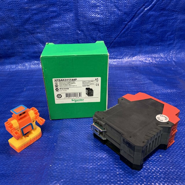
Schneider Electric XPSAK311144P Emergency Stop Relay Module, Preventa, 24V AC/DC eBay

Metric LED Turn Signal Relay goheencycles
Roadtrek 200 electrical schematics & diagrams Class B Forums
'00 FBody + '99 E39 = MY swap Page 8

CE3T10R02 E/STOP 30MM COMPACT TWIST REL W 1NC 0 IPD Industrial Products

CF13GL02 LED Bulb Electronic Flasher Flashers & Load Resistors Car Bulb Installation

Relay Bases 93027024 RELAY BASE Electrical Distributors E Preston Electrical Ltd
My Project, the "FavElec" Page 11 DIY Electric Car Forums

2020 GCU 11R 12V Genset Controller Accessories Relay Module Provides Control Signals To Gen Set

2021 GCU 11R 12V Genset Controller Accessories Relay Module Provides Control Signals To Gen Set
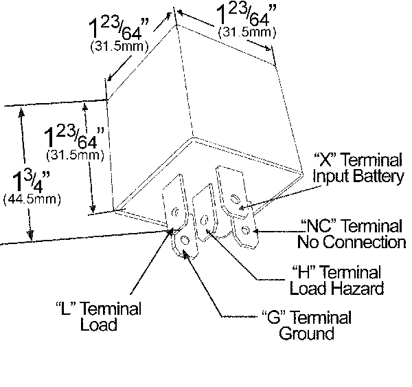
44090 5 Pin Flasher, Electronic LED, ISO Terminals

NasonNason Low Pressure Switch 10 PSI SPST Normally Open with 1/8 in.27 NPT Male Media

2021 GCU 11R 12V Genset Controller Accessories Relay Module Provides Control Signals To Gen Set

3Pin EP28 Electronic LED Flasher Relay Fix Turn Signal Bulbs Hyper Flash Issue eBay
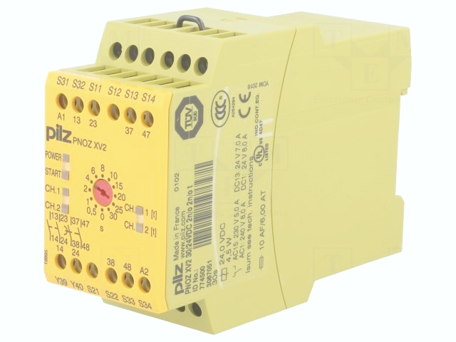
Topic Emergency Stop Switches X On Australia

Schneider Electric XPSAK311144P Emergency Stop Relay Module, Preventa, 24V AC/DC eBay


